Vertex Standard VX-1400 Spezifikationen
Stöbern Sie online oder laden Sie Spezifikationen nach Auto-Videosysteme Vertex Standard VX-1400 herunter. Vertex Standard VX-1400 Specifications Benutzerhandbuch
- Seite / 56
- Inhaltsverzeichnis
- LESEZEICHEN
- OPERATING MANUAL 1
- Table of Contents 2
- VX-1400 QUICK REFERENCE GUIDE 3
- VX-1400 OPERATING MANUAL2 4
- RESET PROCEDURES 4
- 3VX-1400 OPERATING MANUAL 5
- VX-1400 OPERATING MANUAL4 6
- 5VX-1400 OPERATING MANUAL 7
- REAR PANEL CONNECTIONS 8
- SAFETY PRECAUTIONS 10
- INSTALLATION 12
- MOBILE MOUNTING 14
- BASE STATION INSTALLATION 19
- ABLE TYPE 19
- RECEPTION 22
- OPERATION 24
- TRANSMISSION 27
- DUAL WATCH 29
- SELCALL/TELCALL OPERATION 32
- MESSAGE CALL 34
- POSITION REQUEST CALL 35
- POSITION SEND CALL 36
- BEACON REQUEST CALL 37
- ALE OPERATION 40
- MEMORY CHANNEL STORAGE 42
- PROGRAMMABLE FUNCTION BUTTON 44
- ROGRAMMABLE FUNCTION BUTTON 45
- INSTALLATION OF THE OPTION 51
- CT-139 ACCESSORY CABLE 52
- IN ASSIGNMENT 52
- ACCESSORIES & OPTIONS 54
- EC091H102 56
Inhaltsverzeichnis
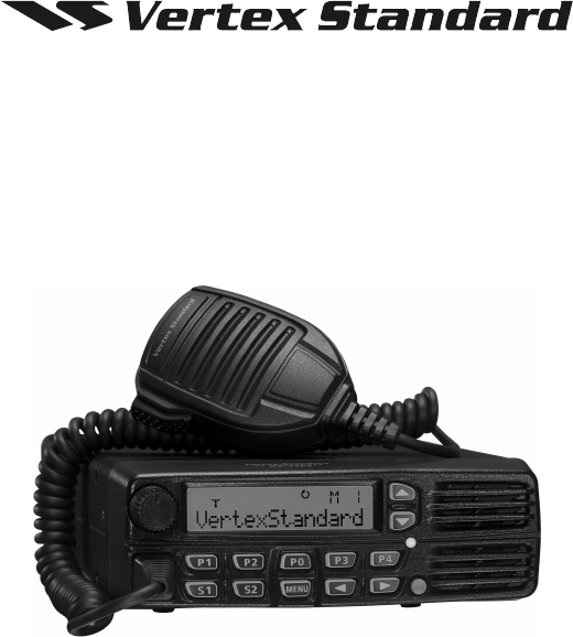
VX-1400OPERATING MANUALVertex Standard LMR, Inc.4-8-8 Nakameguro, Meguro-Ku, Tokyo 153-8644, JapanMH-67A8J Hand Microphone is optional.
VX-1400 OPERATING MANUAL8Antenna PrecautionsAlways locate antennas such that they can never come in contact with outdoor power linesin the event of a
9VX-1400 OPERATING MANUALElectromagnetic Compatibility and RF ExposureIf this transceiver is used with or in the vicinity of a computer or computer-dr
VX-1400 OPERATING MANUAL10POWER REQUIREMENTS AND BASIC INSTALLATIONDC Power ConnectionsThe VX-1400 transceiver is designed for operation from 13.8 Vol
11VX-1400 OPERATING MANUALUse the following procedure to connect the DC cable: Before connecting the DC cable to the battery, measure the voltage acr
VX-1400 OPERATING MANUAL12MOBILE MOUNTINGThe optional MMB-92 Mobile Mounting Bracket allows quick insertion and removal ofthe VX-1400 transceiver from
13VX-1400 OPERATING MANUALThe FC-40 should be located at or near the base of the antenna, so as to minimize lossesand stray radiation. The short lead-
VX-1400 OPERATING MANUAL14Mobile Station GroundingAlthough satisfactory grounding in most installations will be achieved via the DC cable’snegative le
15VX-1400 OPERATING MANUALBASE STATION INSTALLATIONDC Power ConnectionsFor base station installations, Vertex Standard recommends the use of the optio
VX-1400 OPERATING MANUAL16Base Station Antenna ConsiderationsAs with mobile or maritime installations, antenna performance is critical to base station
17VX-1400 OPERATING MANUALdipole at a height of 10 meters could, ionospheric propagation conditions permitting, beexpected to provide outstanding perf
VX-1400 Quick Reference Guide ... 1Button Overview / Re
VX-1400 OPERATING MANUAL18Base Station GroundingThe VX-1400 HF transceiver, like any other HF communications apparatus, requires aneffective ground sy
19VX-1400 OPERATING MANUALTypically, the ground connection consists of one or more 2.4 m (8’) copper-clad steelrods, driven into the ground. If multip
VX-1400 OPERATING MANUAL20TURNING THE TRANSCEIVER “ON” AND “OFF” Be certain that all power supply, antenna, ground, microphone, and other accessoryco
21VX-1400 OPERATING MANUALfrequency (receive frequency vs transmission frequency) will appear on the display. Press the []/[] (move the digit) and
VX-1400 OPERATING MANUAL22OPERATIONFREQUENCY AND CHANNEL SELECTIONThe VX-1400 includes the following frequency selection capabilities: A VFO (Variabl
23VX-1400 OPERATING MANUALVFO Mode Press the []/[] button to select the operat-ing frequency. If the tuning rate is too slow or too fast, the fre-
VX-1400 OPERATING MANUAL24OPERATIONMemory Channel Mode Press the []/[] button to select the desiredMemory Channel within the selected MemoryBank. R
25VX-1400 OPERATING MANUALOPERATIONTRANSMISSION For Voice transmission, close the PTT (Push To Talk) switch on the microphone; thetransmitter will no
VX-1400 OPERATING MANUAL26Antenna Tuning ProceduresWhen the optional FC-30 or FC-40 External Antenna Tuner is installed, it is activated oneach channe
27VX-1400 OPERATING MANUALOPERATIONDUAL WATCHThe Dual Watch feature allows the user or dispatcher to operate on one channel whileperiodically making a
1VX-1400 OPERATING MANUALVX-1400 QUICK REFERENCE GUIDEVOL KNOBAdjusts the audiovolume level.POWER SWITCHPress and hold untilthe LCD display isillumina
VX-1400 OPERATING MANUAL28ENCRYPTED TRANSMISSION / RECEPTION (REQUIRES OPTIONAL ENCRYPTION UNIT) If the transceivers you (and others in your communic
29VX-1400 OPERATING MANUALOPERATION2.182 MHZ EMERGENCY CHANNEL MODEIf the [S1] and [S2] buttons was assigned to “ALARM” and “2182” functions by yourVE
VX-1400 OPERATING MANUAL30SELCALL/TELCALL OPERATIONGENERALThe VX-1400’s Selcall feature provides six calling modes: SelcallThe Selcall mode allows yo
31VX-1400 OPERATING MANUALSELCALLThe Selcall mode allows you to make an individual/group call using an individual ID(Identification) assigned to each
VX-1400 OPERATING MANUAL32SELCALL/TELCALL OPERATIONMESSAGE CALLThe Message Call mode allows you to send a text message (up to 64 characters of text) t
33VX-1400 OPERATING MANUALPOSITION REQUEST CALLThe Position Request Call mode allows you to request position information from a spe-cific station.Prep
VX-1400 OPERATING MANUAL34SELCALL/TELCALL OPERATIONPOSITION SEND CALLThe Position Send Call mode allows you to send your own position information to t
35VX-1400 OPERATING MANUALBEACON REQUEST CALLThe Beacon Request Call mode allows you to inquire as to the signal quality between yourtransceiver and a
VX-1400 OPERATING MANUAL36TELCALLThe Telcall mode allows you to make a telephone call through a telephone interconnectservice provider.Preparation Pr
37VX-1400 OPERATING MANUALSELCALL/TELCALL OPERATIONNOTE
VX-1400 OPERATING MANUAL2RESET PROCEDURESWhen you lose the operation procedure, or if radio operation becomes erratic, youmay reset all settings to th
VX-1400 OPERATING MANUAL38The VX-1400’s ALE (Automatic Link Establishment) feature allows you to select thechannel with the best LQA (Link Quality Ana
39VX-1400 OPERATING MANUALALE OPERATION (REQUIRES OPTIONAL ALE-2 UNIT)Sending an ALE Call with an Imbedded Message Press the []/[] button, as neede
VX-1400 OPERATING MANUAL40The VX-1400 allows the user or dispatcher to store the frequency and operating modeinto the desired Memory Bank. Press the
41VX-1400 OPERATING MANUALMEMORY CHANNEL STORAGE Press the [MW] button, then press the []/[]button to select the desired ATT or RF AMP fea-ture. Av
VX-1400 OPERATING MANUAL42The VX-1400 includes seven Programmable Function ([S1], [S2] & [P0] ~ [P4]) but-tons. The Programmable Function button f
43VX-1400 OPERATING MANUALPROGRAMMABLE FUNCTION BUTTONFUNCTIONUPDOWNLEFTRIGHT1 MHz UP1 MHz DOWNA. NOTCHALEATT/P.AMPCALLCALL1CALL2CALL3CALL4CALL5CH1CH2
VX-1400 OPERATING MANUAL44UPPress the assigned programmable button to increase the operating frequency (while in theVFO mode) or memory channel (while
45VX-1400 OPERATING MANUALCALL1 ~ CALL5Press the assigned programmable button to instantly send the Selcall to the dealer pre-programmed station.CH1 ~
VX-1400 OPERATING MANUAL46FILTERPress the assigned programmable button to enable selecting the receiver bandwidth. Toselect the receiver bandwidth, pr
47VX-1400 OPERATING MANUALPROGRAMMABLE FUNCTION BUTTONSCANPress the assigned programmable button to activate the upward scan. When the scanner isactiv
3VX-1400 OPERATING MANUALGENERALThe Vertex Standard VX-1400 is a low-cost, rugged, small size, integrated HF communi-cations transceiver designed for
VX-1400 OPERATING MANUAL48VOXPress the assigned programmable button to toggle the VOX feature “on” and “off”.The VOX feature provides automatic transm
49VX-1400 OPERATING MANUALINSTALLATION OF THE OPTIONALE-2 AUTOMATIC LINK ESTABLISHMENT UNIT Make sure that the transceiver is off. Remove theDC Power
VX-1400 OPERATING MANUAL50INSTALLATION OF THE OPTIONCT-139 ACCESSORY CABLEThe CT-139 allows connecting the external accessories such as CW Keyer, Data
51VX-1400 OPERATING MANUALINSTALLATION OF THE OPTIONCT-139 ACCESSORY CABLEPIN ASSIGNMENTPIN #12345678910111213141516171819202122232425FUNCTIONAUX I/O-
VX-1400 OPERATING MANUAL52SUPPLIED ACCESSORIES DC Power Cord T9025225 Spare Fuse (25 A Blade Type) Q0000074 Operation Manual Warranty CardAVAILABL
Copyright 2012Vertex Standard LMR, Inc.All rights reserved.No portion of this manualmay be reproducedwithout the permission ofVertex Standard LMR, Inc
VX-1400 OPERATING MANUAL4MIC JackThis modular jack accepts microphone voice input, as well as scanning and PTT (PushTo Talk) control from the micropho
5VX-1400 OPERATING MANUAL[POWER( )] SwitchThis is the main on/off switch for the VX-1400. Press and hold this switch for 2seconds to toggle the transc
VX-1400 OPERATING MANUAL6DC IN 13.8VThis is the main DC power input jack for the VX-1400.ANT JackThis PL-259 (“M” Type) connector is used for connecti
7VX-1400 OPERATING MANUALSAFETY PRECAUTIONSBefore proceeding with installation of the VX-1400 transceiver, please read and observeall safety and opera
© 2020, manymanuals.de. Alle Rechte vorbehalten. | 0.373 s |
 Manymanuals.com
 Manymanuals.de
 Manymanuals.fr
 Manymanuals.it
 Manymanuals.pl
 Manymanuals.cz
 Manymanuals.es
 Manymanuals-pt.com
Kommentare zu diesen Handbüchern